Automotive Suspension Failures
by
Charles C. Roberts, Jr.
Automobile suspension systems are mechanical devices whose
function is to support the vehicle body and other components
above the wheels. There are a variety of designs including coil
spring, longitudinal leaf, transverse leaf, torsion bar, MacPherson,
Christy, and solid axle.

Figure 1 - MacPherson strut suspension

Figure 2 - Solid axle suspension
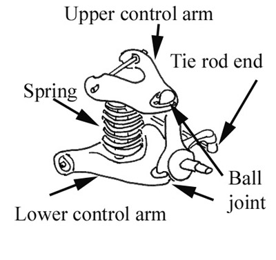
Figure 3 - Control arm suspension with coil springs
Figures 1 through 3 are drawings of typical
suspension systems found on most vehicles on the road. Figure 1 is
the classical MacPherson strut suspension, which is common on
many front drive vehicles. The strut, which is also a shock damper,
moves vertically while the control arm limits transverse and
longitudinal movement. The system is compact, efficient and
adapts easily to front and rear applications. Figure 2 is a view of an
earlier design: the solid axle suspension with king pin. The solid
axle beam is supported by springs and connects to a swiveling axle
via the king pin. This suspension is often used on heavier vehicles
such as trucks and on some older vehicles. Figure 3 depicts a
control arm suspension with coil springs. This independent
suspension system is used on many older and rear wheel drive
vehicles.
Automobile accident investigation may focus on a vehicle's
suspension system, being guided by evidence of possible
malfunction or statements from the insured driver or witnesses.
Automotive suspension failure can be caused by a design defect, a
manufacturing defect, poor maintenance or the accident.
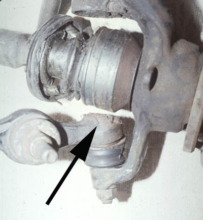
Figure 4
Figure 4 is a view of a MacPherson front suspension on the right
side of a compact car. Evidence suggests that the lower ball joint
(arrow) failed, causing the vehicle to steer uncontrollably, which
resulted in an accident. Figure 5 is a top view of the ball joint
showing wear patterns from the drive shaft rotor just above the ball
joint. The ball joint itself was dry and badly worn with no evidence
of lubrication. The vehicle had over 100,000 miles on the
odometer. The wear on the top of the ball joint suggests that for a
period of time, the joint had failed and had moved vertically and
rubbed against the axle rotor. The rotor was acting as a retainer of
the joint, preventing it from separating from the suspension. This
condition would result in excessive play in the steering, plus a loud
noise that should have acted as a warning to the insured driver that
a problem existed. The driver continued to operate the vehicle until
the accident occurred. The failure of the ball joint was determined
to be maintenance related with no evidence of a manufacturing
defect.
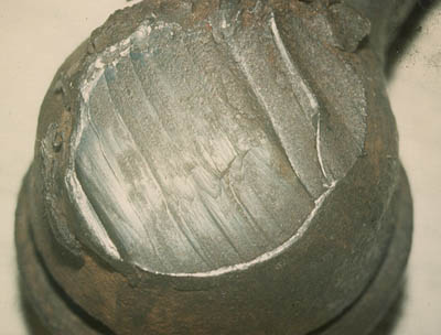
Figure 5
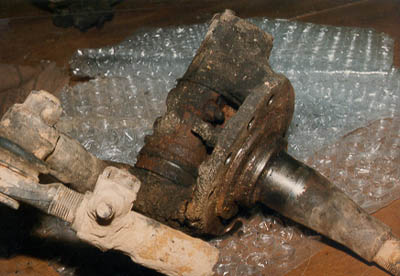
Figure 6
Figure 6 is a view of a king pin assembly from a large road tractor.
Figure 7 is a close-up of a crack in the king pin housing. A truck
driver claimed loss of control while on a winding rural highway.
Analysis of the housing fracture surface indicated that
environmentally assisted cracking had caused the failure. What
initiated the environmentally assisted cracking was severe wear
from lack of lubrication, a maintenance related failure.
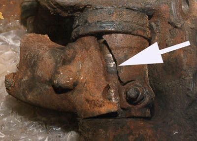
Figure 7
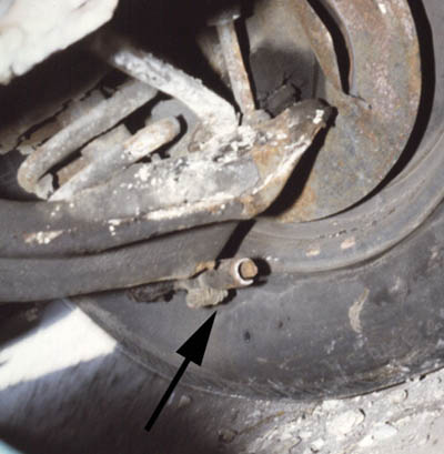
Figure 8
Figure 8 is a view of a front control arm suspension with a
fractured tie rod end. Figure 9 is a close-up of the fracture surface.
The driver indicated that the tie rod end suddenly failed, and an
accident resulted. The lower arrow in Figure 9 points to a corrosion
related crack that had formed through the tubing wall. Despite the
corrosion damage to the tubing, the fracture surface (white area,
upper arrow) is characteristic of a sudden overload, indicating that
a sudden failure under normal conditions was unlikely. The likely
cause would be an impact with a noncompliant object such as a
curb or another vehicle.
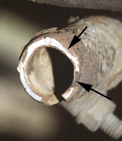
Figure 9
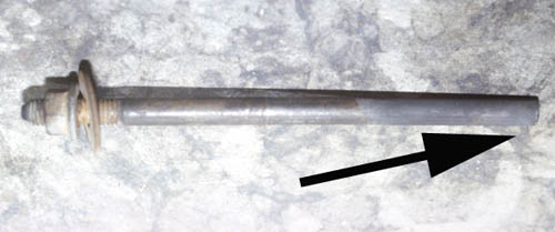
Figure 10
Figure 10 is a view of a rear control arm bolt in a late model front
drive automobile. The driver complained of loss of control, which
resulted in a vehicle rollover and personal injury. The right end of
the bolt had fractured. A close-up of the fracture surface is shown
in Figure 11.
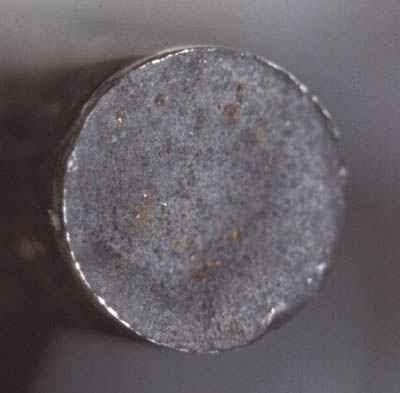
Figure 11
Metallurgical analysis of the part revealed improper heat treating
of the bolt, which was the cause of the failure and was a
manufacturing defect. When the bolt failed, the right rear control
arm parted from the suspension, causing the right rear tire to point
outward at an angle. The ensuing yaw motion terminated with a
vehicle rollover.
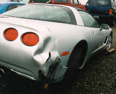
Figure 12
Figure 12 depicts the right rear tire of a vehicle with a severe toe-in
of about 30 degrees. The body damage is characteristic of having
struck another vehicle. The control arm and tie rod end was badly
bent, but not fractured, suggesting that this condition was most
likely a result of the impact.
Suspension systems are often blamed as a cause of an accident.
Driver error can explain many of the accidents, while the
remaining ones can be attributed to poor maintenance, design or
manufacturing defects. Obviously, insurers are interested in causes
of failure that suggest negligent behavior by some other party for
subrogation purposes. If legal action is contemplated, then
potential litigants should be placed on notice as to the existence of
the evidence and a joint protocol developed before any destructive
testing is performed.
FOR TECHNICAL ARTICLES CONTACT CLAIMS MAGAZINE AND ASK
FOR A REPRINT OF A PAST TECHNICAL NOTEBOOK ARTICLE
CLAIMS MAGAZINE