ANALYSIS OF RIGGING RELATED ACCIDENTS
by
Charles C. Roberts, Jr.
Figure 1 is an interesting study of a shifting load on a tractor semi-
trailer. Apparently the rigging or tie downs have not properly secured the load
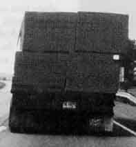
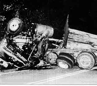
_________________Fig. 1____________________________Fig. 2___________________
which has now shifted its center of gravity more to the right of the vehicle.
This significantly reduces the safety margin associated with this rig in that a
load shift to the right and the right sloped super elevation of the road means
that a sudden evasive maneuver to the left is more likely to cause a vehicle
rollover. Figure 2 shows the result of a load shift on a semi-trailer unit. The
vehicle frame rails, the load being carried by the semi-trailer unit, are
depicted in Figure 3. The vehicle frames were stacked on top of each other with
oak planks as spacers. The frame C-sections tend to press into the wood when
chain binders are used to secure the load. After driving about 20 miles, the

________________ Fig. 3_______________________Fig. 4_________________
driver stopped and tightened the load. Typically truck drivers do this initially
to make sure the load has not shifted and binders have not loosened. After re-
tightening, the load is usually secure until the next stop. The problem with
this load configuration is that the wood continues to crush under the pressure
from the sharp edged frame rails. As the load compressed from road vibration,
the binders loosened. As the vehicle traveled around a sharp corner, the load
shifted causing the trailer to tip and loss of control. The packaging design of
this load should have been redesigned to reduce the propensity to crush and
become unstable.
In many instances the rigging is not the cause of the accident. Figure 4
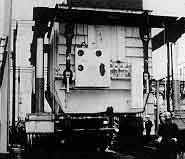
shows a road tractor after the semi-trailer tipped over. Figure 5 shows a large,
top heavy molding machine that was part of the load. During evasive maneuvers in
traffic, the vehicle rolled over. Although the rigging was found to be properly
applied, the top-heavy nature of the load precluded any sudden yaw motion, thus
requiring extreme caution when maneuvering. A top-heavy load can cause an upset
of the vehicle even at speeds as low as 5 miles per hour. If a tractor is making
a sharp turn into a terminal with such a load, suddenly applying the brakes or
suddenly accelerating can cause an upset at low speed.
_________________ Fig. 5_________________________Fig. 6______________________
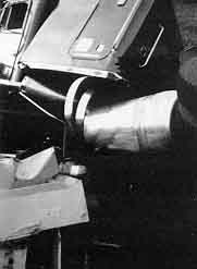
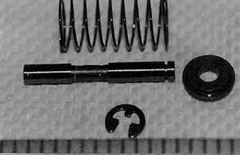
Figure 6 is a view of a large transformer being placed in position. During
the lifting phase the hydraulic rigging failed, causing the transformer to drop.
Figure 7 is a close-up of an hydraulic spool control valve assembly that did not
properly regulate hydraulic pressure to the hydraulic lifts. The small C-clip at
the bottom of the photograph was found to be missing in one of the control valve
assemblies. This resulted in that particular control valve not centering
properly, which caused uncontrolled flow to the main rigging lifts. With one
lift cylinder not lifting, the transformer tipped and fell to the ground,
causing severe damage. This rigging accident was a result of improper assembly
of a control valve.
____________________ Fig. 7__________________________ Fig. 8___________________
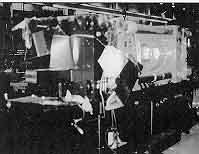
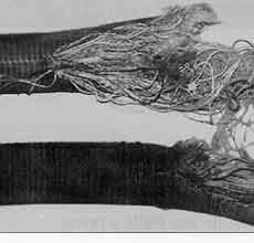
Slings are often used as part of rigging for lifting equipment. Figure 8
shows a sling that failed, causing the load to drop and severe property damage.
Failure analysis of the sling found it to be worn and overloaded. Figure 9 shows
a typical new sling with the load capacity label and warning label. It should be
noted that the load capacity of the sling varied depending on application. The
choker arrangement has a rated capacity of 6300 lbs, while the vertical
arrangement has an 8400 lb rated capacity. Overloading and abusing slings is a
common cause of sling rigging failures.
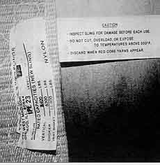
Fig. 9
Rigging related accidents can result in significant property and personal
injury losses. In many instances, basic principles of static force equilibrium
are violated with the aforementioned consequences. In some instances,
deficiencies in rigging design or manufacture are found. Documentation of
witness testimony can be extremely useful in reconstructing rigging accidents.
For instance, information on acoustical emission (creaking) from the load prior
to failure may give clues as to how the accident occurred. Finally, failure
analysis of damaged parts may help answer causal questions, determine extent of
coverage or chance of monetary recovery.
FOR TECHNICAL ARTICLES CONTACT CLAIMS MAGAZINE AND ASK
FOR A REPRINT OF A PAST TECHNICAL NOTEBOOK ARTICLE
CLAIMS MAGAZINE