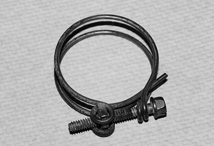
 FIGURE 1
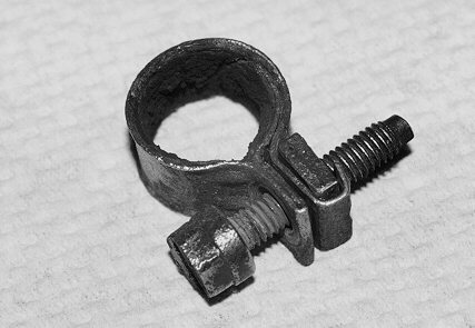 FIGURE 2
 FIGURE 1
 FIGURE 2
material and a slightly different arrangement for the clamping screw mount. The
type D hose clamp (Figure 4) is similar to the type B design with slight differences
in the clamping screw design. The type E hose clamp is an illustration of simplicity,
being constructed of wire without the usage of a screw mechanism to provide
clamping force (Figure 5). Finally the ubiquitous type F hose clamp utilizes a
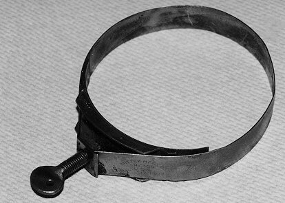 FIGURE 3
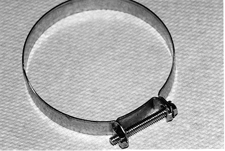 FIGURE 4
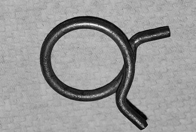 FIGURE 5
screw that directly engages the band material to provide clamping force (Figure 6).
The type F design has the capacity of a wide range of opening diameter, yielding a
flexible design but also an opportunity for misuse. Each of the hose clamps is
designed for a particular hose size. The type E hose clamp in Figure 5 is a nominal
0.875 inches in diameter with a minimum of 0.85 inches and a maximum 0.90
inches. If the hose size is less than 0.85 inches, the hose will not be clamped
properly. Likewise, a hose diameter larger than 0.90 inches would be too large to
be clamped.
Figure 7 shows a hose clamp and fuel tube removed from a vehicle that was
destroyed by fire, as a result of a fuel leak. Apparently, the mechanic providing
carburetor repair service bent the fuel tube while making a repair. The tube was
cut away at the damaged area and a fuel line with type F hose clamp was
substituted as an inexpensive field expedient. As can be seen by the hose clamp
band, it has been over-tightened which tends to extrude rubber through the
opening in the band and causes damage to the fuel hose. Also, it should be noted
that substituting rubber tubing for metal in high temperature environments can
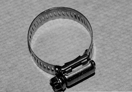 FIGURE 6
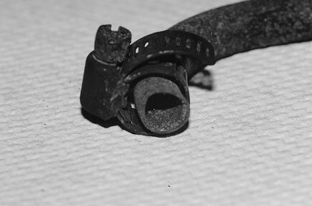 FIGURE 7
result in hose failure (see Claims, May 1992, “Fuel Line Fires May Result from
Poor Maintenance”). In many instances, when fuel is leaking from fuel lines, the
hose clamp is merely tightened until the leak stops. This often results in over-
tightening of the clamp, damage to the fuel hose and a bigger leak. Sometimes a
type F hose clamp is substituted for a type B hose clamp and over-tightened
(which is not possible with a properly selected type B hose clamp), causing a
similar loss. Figure 8 is an example of an over-tightened hose clamp, as evidenced
by the rubber extruding through the band openings.
Figure 9 is a view of a type E hose clamp which was not fully engaged on a barb type fitting. This resulted in water leakage from the upstairs hot tub in a home, causing severe damage throughout the structure. The home was new and the plumber failed to water test all fittings prior to leaving. When the water was turned on in the new unoccupied home, the leak developed, causing the loss.
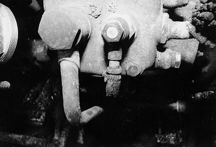 FIGURE 8
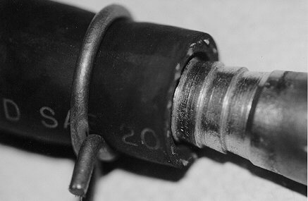 FIGURE 9
Although simple mechanical devices, hose clamps can be involved in significant water losses, especially where electronic and computer equipment is involved (see Insurance Adjuster, November 1982, “Adjusting Water Damaged Computer Equipment”). Many of the failures are a result of installation problems such as improper application or over/under tightening of the clamp. In some cases, manufacturing deficiencies lead to failures. Finally, design related failures, including corrosion (see Claims, September 1993, “Metallic Corrosion”) do occur but to a lesser extent.