FIRE LOSS FROM IMPROPER HALOGEN FLOODLIGHT
INSTALLATION
By
Charles C. Roberts
Halogen floodlights have been used in both residential and
industrial applications for years. They are characterized by high
light intensity on task and high heat dissipation.
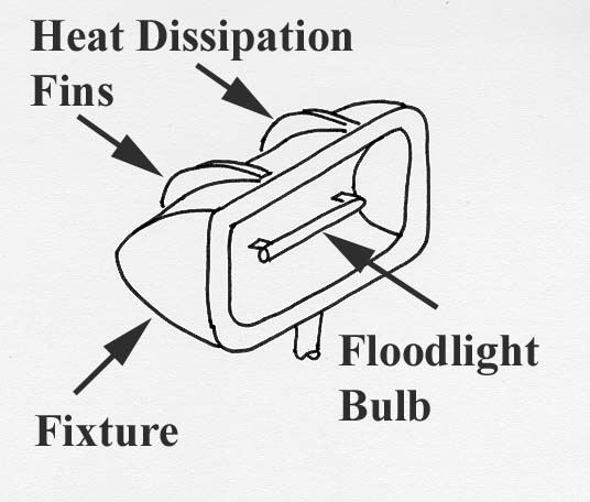
Figure 1
Figure 1 is a drawing of a typical halogen light fixture. The fixture
frame supports a receptacle for a cylindrical halogen bulb, which is
protected from the weather by a lens and seal. The bulbs are very
warm, and cooling fins are usually molded into the back of the
fixture to help dissipate the heat. Most manufactures warn against
placing these fixtures too close to combustible materials because of
the obvious fire hazard, which leads us to the subject matter of this
article.

Figure 2
Figure 2 is a large feed storage facility that was badly damaged by
a fire that nearly consumed the roof. The arrow points to a fire
origin at an eave in the vicinity of newly installed flood light
fixtures. The fixture at the origin was badly damaged. Figure 3 is a
view of another light fixture that had been installed in the storage
area. There were no other ignition sources in the area, other than
the electrical fixtures, since the building was not heated. The
fixtures were mounted in an unusual way.
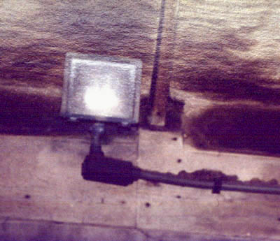
Figure 3
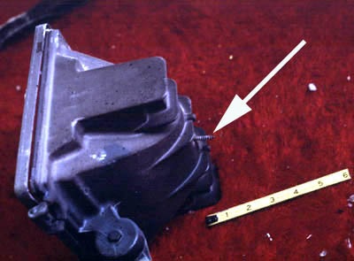
Figure 4
Figure 4 shows one of the unburned fixtures removed for
inspection. A hole had been drilled in the back of the halogen flood
lamp heat sink and a screw inserted to secure the fixture to the
wood structure near the eaves.
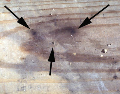
Figure 5
Figure 5 shows the wood joist where the fixture had been mounted.
The middle arrow is the screw hole while the two dark areas (left
and right arrows) are parts of the heat sink that had pressed against
the wood. The dark regions are advanced stages of pyrolysis:
indicating that significant heating of the wood has occurred, drying
it out, reducing ignition temperature and creating conditions for
ignition. Inquiry as to the reason for the unusual mounting method
of the lighting fixtures resulted in the following explanation. The
lighting had been installed with proper clearance between the
fixture and wood at a lower level on the wall by an electrical
contractor. Several fixtures had been damaged by piles of feed that
were being pushed up against the wall as shown in Figure 6. In
order to eliminate the problem, the fixtures were moved by the
facility’s maintenance people, to a location higher on the wall and
secured using a wood screw in an attempt to make a sturdier
fixture mount.
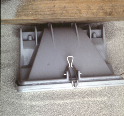
Figure 6
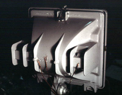
Figure 7
Figure 7 shows the back heat sink area of the fixture. Figure 8 is an
infrared thermogram showing significant heating of the heat sink
on the back of the fixture. The rear heat sink is the hottest surface
on the fixture and was attached to a wood structural member using
a wood screw. Apparently, one of the fixtures eventually ignited
the wood joist and adjoining roof structure, resulting in the loss. It
should be noted that pushing the feed up around the fixture as
shown in Figure 6 aggravates this condition by reducing heat
transfer from the fixture.
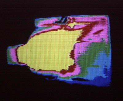
Figure 8
Most manufacturers of halogen flood lamps warn about the fire
hazards of insufficient clearance between the fixture and
combustible materials. Ignoring these recommendations can
precipitate a significant fire loss as illustrated by this field
expedient.