by
Charles C. Roberts Jr.
Steel cable or wire rope is used throughout industry, providing a variety of tasks
such as structural support, lifting and control functions. Figure 1 is a view of a
typical wire rope showing many steel wire strands woven in a manner similar to
regular hemp rope. Wire rope is very strong for its size and weight and performs
many functions well. However, it is susceptible to corrosion, wear and metal
fatigue, which can cause failure, economic loss and personal injury.

FIGURE 1

FIGURE 2
Figure 2 shows a wire rope loop, complete with compression sleeve and thimble.
The purpose of the thimble is to provide a surface that withstands wear better than
the bare wires. Without the thimble, the wire strands would eventually abrade or
fatigue causing a failure. The compression sleeve keeps the wire from sliding
around the thimble. Sometimes mechanical clamps are used, especially for large
wire ropes.

FIGURE 3

FIGURE 4
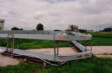
Figure 3 is a view of a large grain auger that collapsed during a windstorm.
Peak wind speeds were approximately 50 MPH, a speed easily resisted by the
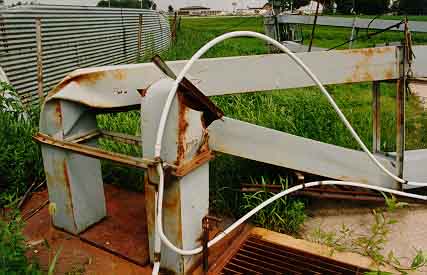
structure. Figure 4 is a view of the upper portion of the tower. Inspection of the
cable indicated that a cable failure had occurred in the upwind cable. Figure 5
shows the cable loop that had failed at a pier in the ground. Several wire strands
had been broken. The cable clamp was adequate, but no thimble had been
provided. None of the other cables had a thimble at the loop end. Figure 6 is a
close-up of failed strands at the end of the loop. Failure analysis of the strands
suggested that corrosion fatigue was the likely cause of failure. This was brought
on by the lack of a thimble that would have protected the cable end. It was
concluded that this failure was a result of improper construction of the tower
cable system.

FIGURE 5

FIGURE 6
Overloading of cable systems is a common cause of failure. Serious injury can
occur if a cable fails near personnel. For instance, if a wire rope cable fails when
lifting or winching a load, the cable often whips violently and can cause serious
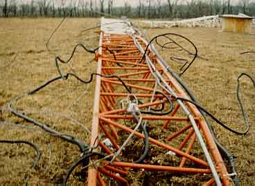
injury. Figure 7 is a view of a radio tower that collapsed during an ice storm. The
cable failure origin showed evidence of severe overloading in an otherwise
properly designed and maintained cable system.

FIGURE 7
When inspecting for the cause of a cable failure, it is desirable to save the failed
cable, especially the failure origin, for future analysis. Inquire as to the loading on
the cable, i.e., wind, lifting, high-speed operation, etc. If abrasion or wear is a
cause of the failure, analysis of the design or manufacturing method is in order.
Other design considerations may also be a cause of failure, especially in those
cases where excessive rope flexing occurs from using cable sheaves (pulleys) that
are too small for the wire rope.
FOR TECHNICAL ARTICLES CONTACT CLAIMS MAGAZINE AND ASK
FOR A REPRINT OF A PAST TECHNICAL NOTEBOOK ARTICLE
CLAIMS MAGAZINE
BACK TO C. ROBERTS CONSULTING ENGINEERS HOME PAGE,
WWW.CROBERTS.COM

FIGURE 1

FIGURE 2

FIGURE 3

FIGURE 4

FIGURE 5

FIGURE 6

FIGURE 7
FOR TECHNICAL ARTICLES CONTACT CLAIMS MAGAZINE AND ASK
FOR A REPRINT OF A PAST TECHNICAL NOTEBOOK ARTICLE
CLAIMS MAGAZINEWWW.CROBERTS.COM