THERMAL PATTERN ANALYSIS -
AN IMPORTANT INGREDIENT IN
FIRE INVESTIGATION
By
Charles C. Roberts, Jr.
After a fire, thermal patterns remaining at a fire scene are an
important ingredient in fire investigation. Charred wood, soot
deposition, melting, spalling and structural deformation are
examples of thermal patterns caused by fires. When performing
fire cause/origin analysis, fire investigators often seek out thermal
patterns to aid in determination of the fire origin. The following
article is a mini-encyclopedia of examples of thermal patterns
along with what can and cannot be gleaned from the analysis of
thermal patterns.

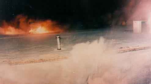
Figure 1a Classic V-pattern
Figure 1a depicts the classic V-pattern relied upon by many
investigators. When hot gases from a fire rise in a natural
convection mode, (as a result of heat related gas buoyancy) the
gases tend to spread out as they rise, forming a V. Consequently,
the fire investigator looks to the base of the V as the origin of the
fire. In Figure 1a, the soot pattern, on the walls of the home, has
spread outward near the eaves, suggesting that the fire origin is at
grade level (arrow). Soot patterns inside the home were less severe,
suggesting that the fire started on the outside of the wall.
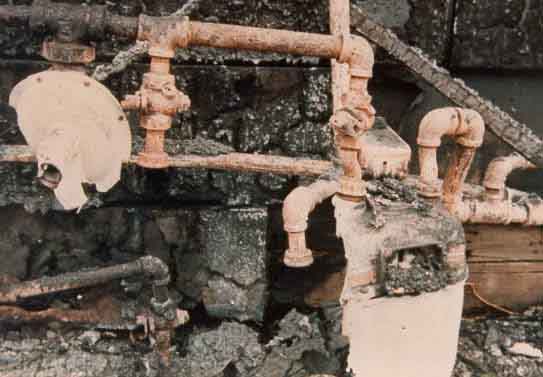
Figure 1b Melted gas meter and pressure regulator
A closer look, at the base of the V, shows burned gas piping as
shown in Figure 1b. Severe charring of wood and melted
aluminum casings are indicative of a fire origin in this vicinity. It
was determined that frost heaving caused movement of the natural
gas piping, resulting in gas leakage through a compression fitting.
The exact ignition source was undetermined. A possible ignition
source could be a water heater, just inside the wall, igniting the
natural gas before an explosive volume of gas could have
accumulated. Air infiltration is a typical avenue for natural gas to
enter a home, especially in the winter.
Figure 2 is a view of another classic V-pattern in a kitchen. The
pattern is typical of an overheated appliance on the kitchen
countertop. The arrow points to severely burned wallboard at the
base of the V-pattern where a decomposed, plastic coffee pot
housing was found, the apparent cause of the fire.
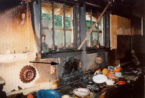
Figure 2 Kitchen fire

Figure 3 Propane gas leakage causes a fire
Propane gas is heavier than air and can cause random burn patterns
throughout a building, provided there is sufficient venting of the
deflagration so that an explosion does not occur. In Figure 3, the
propane cylinder on the fork truck (far left arrow) leaked, resulting
in pooling of propane gas on the floor. A water heater pilot light is
the likely ignition source of the propane. After ignition, random
pools of propane ignited, causing multiple V-patterns as shown by
the arrows on the right side of the photo. The amount of propane
released before ignition was small, unable to sustain an explosion,
but sufficient to cause random burning throughout the building,
depending on the amount trapped in areas throughout the building.
Multiple V-pattern observation is often a tenet of an opinion by an
arson investigator that a fire of incendiary cause has occurred.
Although multiple V-patterns have occurred in this example, the
nature of the patterns is unique to propane gas accumulation and is
not necessarily an arson.

Figure 4 Electro discharge milling machine
Machine shops often use numerically controlled, electro discharge,
milling machines. These machines use electrical arcs to erode
away metal on the work piece to manufacture a finished part. The
electrode and work piece are submerged in a dielectric oil for
cooling and reduced oxidation of the electrode head. The machines
run on a computer program and are often left running overnight,
unattended. If the oil level drops below the electrical arc, ignition
of the oil can occur, causing a smoky fire. A float switch is
designed to shut off the machine, if the oil level drops below a
predetermined level. Figure 4 is a view of an EDM machine that
was left operating overnight. A fire resulted, virtually destroying
the building. Burn patterns on the side of the oil reservoir reflect a
low oil level (arrow). The oil in the reservoir tends to cool the side
of the tank, showing a different oxidation pattern than the upper
side of the tank where high temperature oxidation is noted. A
failure of the float switch is a possible cause of this fire.
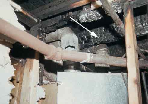
Figure 5 Char depth
Wood char depth is a burn-related pattern utilized by fire
investigators. In Figure 5 the charring of wood joists, often called
alligatoring, is a clue to the fire origin. The arrow shows the most
severe char depth right above the furnace flue pipe, a typical
consequence of flue pipes situated too close to combustible
materials. Heating of the wood, over time, tends to lower its
ignition temperature until it is ignited as a result of heat transfer
from the flue pipe.
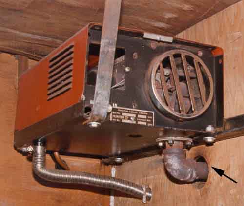
Figure 6a Before the fire
Figure 6a is a view of a propane gas fired heater in a produce
truck, used to keep produce from freezing in the winter. The arrow
points to pyrophoric decomposition of the wood near the heater
exhaust. The discoloration of the wood is an indication that
ignition of the plywood sheathing is eminent. Figure 6b is a view
of a heater in an identical truck that caught fire, destroying the
produce and part of the van. The arrow points to the area where the
plywood sheathing had been installed. In this vehicle, pyrophoric
decomposition of the wood has reduced the ignition temperature to
nearly that of the exhaust pipe, resulting in the fire.
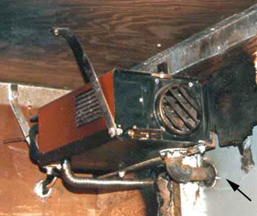
Figure 6b After the fire
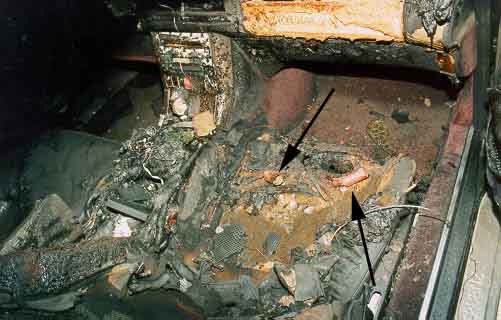
Figure 7 Passenger seat auto fire
Figure 7 is a view of the passenger seat in a 4-door sedan. Burn
patterns tend to focus on the seat as an origin of the fire. Melted
polymers, such as polyurethane, are evident on the seat and dash.
The damage to the dash is most likely a result of a fire on the seat.
The vehicle was found in this condition, with the fire self-
extinguished from lack of oxygen (doors closed). Arrows point to
remains of emergency flares near the center of the seat. There are
no vehicle related ignition sources in that area. Is arson ruled out in
this case? Probably not, since spontaneous ignition of road flares
on seating in automobiles is unlikely.
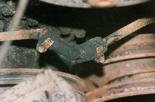
Figure 8 Fuel line repair
Burn patterns may not always point to the actual square inch where
an ignition occurred. Fuel leakage in a vehicle, typically sprays
fuel throughout the engine compartment, causing a diffuse burn
pattern. Inspection of the fuel lines may show deficiencies that are
causative to the fire, as shown by the improper fuel tube repair in
Figure 8. (See Fuel Line Failures, Claims Magazine, May 1992)

Figure 9 Fire remains in a dishwasher
Smoke damage occurred to a home as a result of soot evolution
from a dishwasher. The dishwasher was in the drying cycle at the
time of the fire. A view inside the washing compartment yields
thermal patterns that are clues to the fire cause. The most severely
burned area in the compartment is shown near a collection of
utensils. The upper arrow, in Figure 9, shows a steak knife with the
wood handle burned away. The lower arrow points to the heating
coil used in the drying cycle. Thermal patterns are consistent with
one of the steak knife handles being ignited by the hot drying coil
in the washer.
Figure 10 shows a 100-foot extension cord wrapped in a neat coil
and placed on a rug. The homeowner had connected a new
dehumidifier to the cord in a finished basement. Thermal pattern
analysis indicated melting of insulating material on the extension
cord. There was smoke damage to the home, but no other areas
suffered the degree of melted polymer than the electrical cord.
Apparently, the extension cord was too long for the appliance,
causing a voltage drop and resistive heating. The coil, itself,
limited heat transfer from the wiring. The consequences were
increased heating and increased electrical resistance, resulting in
ignition of the insulation material and carpeting.

Figure 10 Extension cord coil
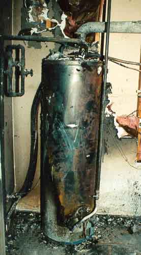
Figure 11 Typical gas fired water heater
Burn patterns on water heaters are dramatic, in that one views a
gradation of thermal patterns from the bright white of the original
painted surface to the severely corroded, oxidized, sheet metal.
Figure 11 depicts a typical V pattern with the base of the V near
the gas valve. Caution should be exercised when interpreting such
a thermal pattern. Possibilities of the fire cause are gas valve
failure, gas pipe leakage, combustible materials placed too close to
the heater, and flame rollout. In the case of Figure 11, flame rollout
ignited nearby garbage bags.
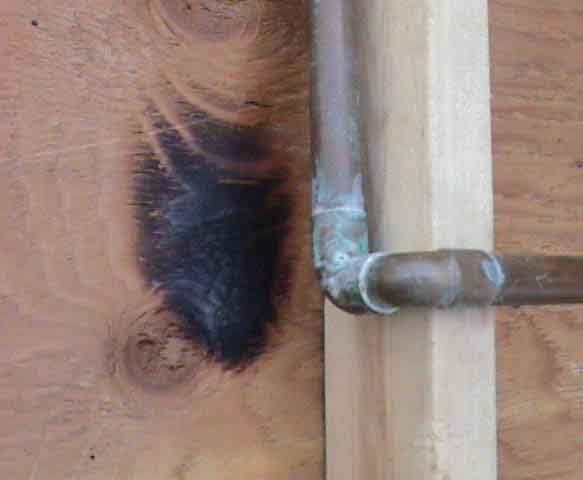
Figure 12 Burn pattern near pipe joint
One large loss involving a 2-story home occurred during the
winter, while the owners were on vacation. Approximately 6
inches of water was found in the basement as well as water vapor
throughout the home. Wallboard had deteriorated and fallen from
wall studs exposing several burned areas, like that shown in Figure
12. Some investigators were interpreting the burned areas at the
pipe joints to be a result of a malfunction of the water heater. What
had actually occurred, was a freeze failure of a few wall-mounted
water pipes during unusually cold weather. This caused hot water
to run through the pipe fractures into the basement, generating the
large amount of water vapor that damaged the drywall. The burn
patterns at the pipe joints, were formed during construction of the
building when plumbers soldered the pipes with torches and were
unrelated to the loss.

Figure 13 The grounder
Some thermal patterns yield inconclusive results, such as the
“grounder’ shown in Figure 13. The destruction is so widespread
that pinpointing the fire origin, based on thermal patterns, is
difficult. Other thermal patterns can be more definitive, as
evidenced by previous examples. Thermal pattern recognition and
interpretation will most likely remain a significant ingredient in
fire cause/origin analysis.
FOR TECHNICAL ARTICLES CONTACT CLAIMS MAGAZINE AND ASK
FOR A REPRINT OF A PAST TECHNICAL NOTEBOOK ARTICLE
CLAIMS MAGAZINE