WATERCRAFT NOMENCLATURE
Bow - Front of craft
Starboard Side - Right side of craft looking forward
Stern - Rear of craft
Port Side - Left side of craft looking forward
Hull - The main body of the craft.
Inboard Motor - A propulsion design where the engine is inside the hull with a propeller shaft extending through the hull to a fixed propeller mount
Inboard/Outboard Motor -, A propulsion design where the engine is at the rear of the hull with a drive shaft extending to a movable propeller housing unit that can be raised or lowered. Often called IO drive.
Outboard Motor - A propulsion design where the motor and propeller shaft unit is mounted on the stern and is outside the hull.
Jet Boat - A craft with a propulsion system using a water pump as opposed to a propeller. Planing Mode - Hull is at sufficient speed to be supported by dynamic forces and skip across the water like a water skier.
Displacement Mode - Hull is supported by buoyant forces caused by water displacement. PFD - Personal flotation device (life jacket, etc.)
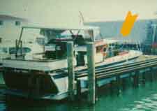
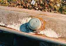
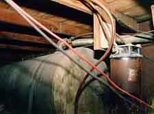
____________Figure 1_________________Figure 2____________________Figure 3__________
Fires and explosions are common loss scenarios when dealing with watercraft. Figure 1 is a view of a typical express cruiser that had sustained an explosion immediately after refueling. As shown in Figure 1, the windows on the front cabin have been blown outward. Figure 2 is a view of the fueling port on the cruiser. Figure 3 is a view of fuel lines under the main deck. Apparently, during fueling operations, gasoline leaked from a fuel fitting into the bilge resulting in the evolution of fuel vapors. The vapors were ignited by various electrical sources associated with the inboard engine, also located in the bilge area. The boat operator failed to engage the ventilation blowers and when the engines were started, the explosion occurred. The explosive ignition source was most likely electrical in nature.
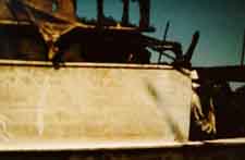
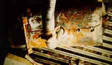
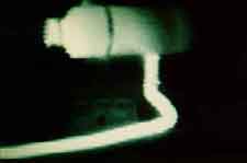
____________Figure 4_________________Figure 5____________________Figure 6__________
Figure 4 shows the remains of a hull that was salvaged after a fire loss. On a cold, windy day the 56 foot cabin cruiser sustained a severe fire that gutted the hull, causing it to sink in approximately 20 feet of water. Before sinking, the fire transferred downwind to several other similar cabin cruisers that were docked nearby, resulting in a substantial loss. When spring arrived, the suspect craft was salvaged and inspected. Figure 5 is a view of a diesel heater that was operating onboard the vessel prior to the fire. According to the owner, the diesel heater thermostat was jumpered so that it would run continuously. The diesel heater had an exhaust pipe that was mounted through the hull about 2 feet above the water line. Examination of the heater showed a "home made" through the hull exhaust fitting. The exhaust fitting provided little thermal protection to the wood hull. Burn patterns on the hull suggested that the through the hull exhaust fitting was at the origin of the fire. Figure 6 is an infrared thermogram of a test heater (light is hot, dark is cold). The exhaust pipe is shown at the bottom and to the left in the thermogram. Temperatures in excess of 500 F were measured, suggesting that the "home made" through the hull exhaust fitting was inadequate to protect the wood hull from fire. In this case, the owner had improperly installed the heater.
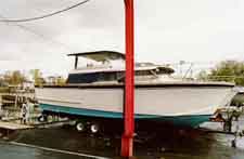
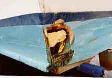
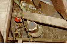
____________Figure 7_________________Figure 8____________________Figure 9__________
Figure 7 is a view of a cabin cruiser that sank at its mooring on a calm summer day. Inspection of the hull after salvage shows severe hull rot and attempts to repair using polyurethane foam (Figure 8). Figure 9 is a view of the bilge pump which shows a "bath tub ring," evidence of high water in the bilge. As indicated by the obvious poor state of hull condition, the craft most likely leaked severely, causing the battery operated bilge pump to draw down the battery. After the pump stopped, the hull settled quickly as more openings in the hull became conduits for water leakage. This loss was most likely owner maintenance related.
Another category of watercraft loss involves collisions with other craft or noncompliant objects such as piers or breakwaters. Figure 10 is a view of a runabout that struck a jetty during the night while in planing mode. Alcohol usage on the part of the boat operator was confirmed via blood testing. Figure 11 shows hull impact damage. Figure 12 is a view of the wheelhouse showing severe forward deformation to the steering wheel, most likely a result of operator impact.
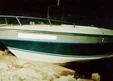
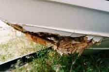
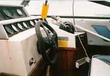
____________Figure 10_________________Figure 11____________________Figure 12__________
Figure 13 is a view of a typical custom high-speed runabout, sometimes called a drag boat because of the tremendous power to weight ratio of the design. This boat was traveling across a lake at full throttle when the operator realized the throttle had stuck in the wide open position. Rather than "kill" the ignition, the operator panicked and abandoned ship. Unfortunately, his passenger was thrown from the craft and did not survive an impact with the shore. Figure 14 is a view of the four-barrel carburetor assembly and throttle linkages. Inspection revealed that the throttle linkage had a propensity to jam at full throttle because of an improper adjustment of the linkage. Improper mechanical maintenance is the likely cause of this mishap.
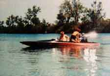
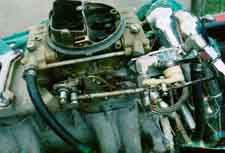
____________Figure 13_________________Figure 14___________________
Reconstructing boating related accidents can be difficult because wrecked watercraft may float out of position and critical evidentiary parts may be lost in the water. Documentation from police or Coast Guard authorities obviously helps in the investigation. Salvage, preservation, and inspection of the vessel can yield valuable information as to the cause of loss.
FOR TECHNICAL ARTICLES CONTACT CLAIMS MAGAZINE AND ASK
FOR A REPRINT OF A PAST TECHNICAL NOTEBOOK ARTICLE
CLAIMS MAGAZINE
BACK TO C. ROBERTS CONSULTING ENGINEERS HOME PAGE,
WWW.CROBERTS.COM
Figure 4 shows the remains of a hull that was salvaged after a fire loss. On a cold, windy day the 56 foot cabin cruiser sustained a severe fire that gutted the hull, causing it to sink in approximately 20 feet of water. Before sinking, the fire transferred downwind to several other similar cabin cruisers that were docked nearby, resulting in a substantial loss. When spring arrived, the suspect craft was salvaged and inspected. Figure 5 is a view of a diesel heater that was operating onboard the vessel prior to the fire. According to the owner, the diesel heater thermostat was jumpered so that it would run continuously. The diesel heater had an exhaust pipe that was mounted through the hull about 2 feet above the water line. Examination of the heater showed a "home made" through the hull exhaust fitting. The exhaust fitting provided little thermal protection to the wood hull. Burn patterns on the hull suggested that the through the hull exhaust fitting was at the origin of the fire. Figure 6 is an infrared thermogram of a test heater (light is hot, dark is cold). The exhaust pipe is shown at the bottom and to the left in the thermogram. Temperatures in excess of 500 F were measured, suggesting that the "home made" through the hull exhaust fitting was inadequate to protect the wood hull from fire. In this case, the owner had improperly installed the heater.


____________Figure 7_________________Figure 8____________________Figure 9__________
Figure 7 is a view of a cabin cruiser that sank at its mooring on a calm summer day. Inspection of the hull after salvage shows severe hull rot and attempts to repair using polyurethane foam (Figure 8). Figure 9 is a view of the bilge pump which shows a "bath tub ring," evidence of high water in the bilge. As indicated by the obvious poor state of hull condition, the craft most likely leaked severely, causing the battery operated bilge pump to draw down the battery. After the pump stopped, the hull settled quickly as more openings in the hull became conduits for water leakage. This loss was most likely owner maintenance related.
Another category of watercraft loss involves collisions with other craft or noncompliant objects such as piers or breakwaters. Figure 10 is a view of a runabout that struck a jetty during the night while in planing mode. Alcohol usage on the part of the boat operator was confirmed via blood testing. Figure 11 shows hull impact damage. Figure 12 is a view of the wheelhouse showing severe forward deformation to the steering wheel, most likely a result of operator impact.


____________Figure 10_________________Figure 11____________________Figure 12__________
Figure 13 is a view of a typical custom high-speed runabout, sometimes called a drag boat because of the tremendous power to weight ratio of the design. This boat was traveling across a lake at full throttle when the operator realized the throttle had stuck in the wide open position. Rather than "kill" the ignition, the operator panicked and abandoned ship. Unfortunately, his passenger was thrown from the craft and did not survive an impact with the shore. Figure 14 is a view of the four-barrel carburetor assembly and throttle linkages. Inspection revealed that the throttle linkage had a propensity to jam at full throttle because of an improper adjustment of the linkage. Improper mechanical maintenance is the likely cause of this mishap.


____________Figure 13_________________Figure 14___________________
Reconstructing boating related accidents can be difficult because wrecked watercraft may float out of position and critical evidentiary parts may be lost in the water. Documentation from police or Coast Guard authorities obviously helps in the investigation. Salvage, preservation, and inspection of the vessel can yield valuable information as to the cause of loss.
FOR TECHNICAL ARTICLES CONTACT CLAIMS MAGAZINE AND ASK
FOR A REPRINT OF A PAST TECHNICAL NOTEBOOK ARTICLE
CLAIMS MAGAZINE
BACK TO C. ROBERTS CONSULTING ENGINEERS HOME PAGE,
WWW.CROBERTS.COM
Figure 13 is a view of a typical custom high-speed runabout, sometimes called a drag boat because of the tremendous power to weight ratio of the design. This boat was traveling across a lake at full throttle when the operator realized the throttle had stuck in the wide open position. Rather than "kill" the ignition, the operator panicked and abandoned ship. Unfortunately, his passenger was thrown from the craft and did not survive an impact with the shore. Figure 14 is a view of the four-barrel carburetor assembly and throttle linkages. Inspection revealed that the throttle linkage had a propensity to jam at full throttle because of an improper adjustment of the linkage. Improper mechanical maintenance is the likely cause of this mishap.


____________Figure 13_________________Figure 14___________________
Reconstructing boating related accidents can be difficult because wrecked watercraft may float out of position and critical evidentiary parts may be lost in the water. Documentation from police or Coast Guard authorities obviously helps in the investigation. Salvage, preservation, and inspection of the vessel can yield valuable information as to the cause of loss.
FOR TECHNICAL ARTICLES CONTACT CLAIMS MAGAZINE AND ASK
FOR A REPRINT OF A PAST TECHNICAL NOTEBOOK ARTICLE
CLAIMS MAGAZINE
BACK TO C. ROBERTS CONSULTING ENGINEERS HOME PAGE,
WWW.CROBERTS.COM
FOR TECHNICAL ARTICLES CONTACT CLAIMS MAGAZINE AND ASK
FOR A REPRINT OF A PAST TECHNICAL NOTEBOOK ARTICLE
CLAIMS MAGAZINEWWW.CROBERTS.COM