CLAIMS ISSUES AND THE SUPPLEMENTAL
INDIVIDUAL RESTRAINT SYSTEM (AIRBAG)
by
Charles C. Roberts, Jr.
INTRODUCTION
Supplemental individual restraints (air bags) are
installed on most present-day vehicles. The modern
air bag control computers (sensing diagnostic
modules) store pre crash vehicular information such
as speed and brake application. The deployment or
non-deployment of these devices raises several
claims related issues, such as: should the device
have deployed in such a minor accident; why didn’t
the device deploy in such a severe accident; and
why was the insured injured from the air bag. These
issues can often be explained by vehicle inspection
and diagnostic testing.
HISTORY OF THE AIRBAG
The first patent issued regarding a deployable
frontal impact protective device was issued in 1935.
An example of the forerunner to the airbag is shown
in Figure1: a drawing based on C. L. Straith’s 1937
patent # 2091057. This was essentially a spring
loaded cushion that would be freed at the release
point during an accident, theoretically restraining
the occupant.
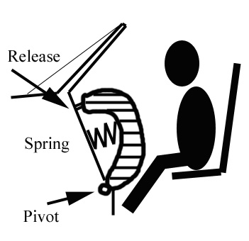
Figure 1 Drawing based on Straith patent #:2091057
August 24, 1937.
In 1953, John Hetrick and in 1958, H. A. Bertrand
(Figure 2) patented the concept of the inflatable
protective air bag system, which resembles present-
day air bags. In 1964, Dr. Carl Clark published
experimental data, which was funded by NASA, on
an inflatable device called the “Airstop” system,
significantly enhancing understanding of the
technology. In 1966, the National Highway Traffic
Safety Administration was created to develop
automobile safety standards and, in the early
1970’s, promoted air bag technology as a means of
reducing the severity of frontal crashes to vehicle
occupants.
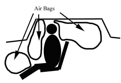
Figure 2 Drawing based on Bertrand patent #:2834606
May 13, 1958
HOW PRESENT DAY SYSTEMS WORK
Figures 3 and 4 are drawings of the two major
system designs: the multi-point sensor system and
the single point sensor system. The multi-point
sensor system incorporates crash sensing devices
placed at a distance from the diagnostic module that
control the air bag deployment based on calibrations
unique to the vehicle. The sensing devices are
acceleration measuring sensors called
accelerometers and are typically located at the front
of the engine compartment for steering column
airbag deployment. The accelerometer information
is analyzed by a computer program in the sensing
diagnostic module and makes the deployment
decision within 50 milliseconds. The single point
sensor system has the accelerometers inside the
control module with no remote wiring to sensors.
The principal direction of force of impact plays a
significant role in deployment. A frontal barrier
crash in excess of about 10 miles per hour will
result in the steering column air bag deployment,
since the principal direction of force is along the
long axis of the vehicle and toward the rear. In a “T-
bone” type side crash where the principal direction
of force is 90 degrees to the long axis of the vehicle,
the steering column air bag will most likely not
deploy, since the cushioning effect of the air bag is
not necessary because the driver is moving laterally.
This reduces the chance of injury from an unneeded
deployment. It should be noted that an occupant of a
vehicle can be injured by an air bag deployment,
especially if that person is small of stature and out
of position, hence the warning on the visor to
remain in a driving position.
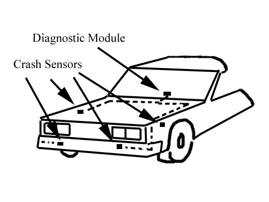
Figure 3 Multi-point sensor system
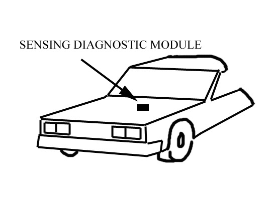
Figure 4 Single point sensor system
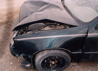
Figure 5
Figure 5 shows a typical frontal impact with the
principal direction of force along the long axis of
the vehicle. Figure 6 shows the deployed driver’s
airbag indicating crash sensors saw sufficient
deceleration to deploy.
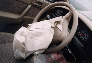
Figure 6
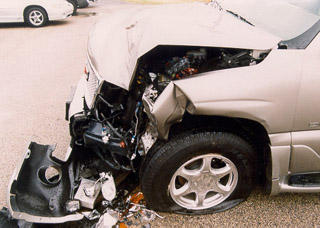
Figure 7
Figure 7 is a view of an impact to the left front
fender of a vehicle. The principal direction of the
force is to the right of the vehicle and at nearly a
right angle to the long axis of the vehicle, which is
outside of the range of allowed deployment for a
frontal airbag. Although there was considerable
damage to the front of the vehicle, the airbag did
not deploy (Figure 8).
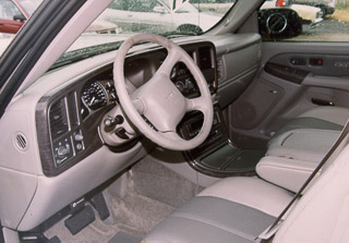
Figure 8
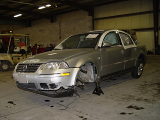
Figure 9
Figures 9 & 10 are views of a side impact to the
front of a vehicle. Figure 10 shows the interior and
the deployed side air bags. Note that the steering
column air bag did not deploy since the principal
direction of force was lateral to the long axis of the
vehicle.
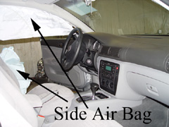
Figure 10
VEHICLE DATA RETRIEVAL (QUERY THE BLACK BOX)
Since 1974, General Motors airbag equipped
vehicles have recorded data on deployment and near
deployment of air bags in the memory of the on-
board sensing diagnostic modules (black box).
Recently, software and hardware interface modules
have become available to collect this data as shown
in Figure 11. The US Government has encouraged
the acquisition of crash data for research purposes
and has encouraged all vehicle manufacturers to
make this data available through the standard
vehicle electronic interface. Another aspect of this
crash data that has not gone unnoticed is its
usefulness in accident reconstruction. In Figure 11 a
laptop downloads data from the air bag sensing
diagnostic module through the vehicle interface,
using an interface processor.
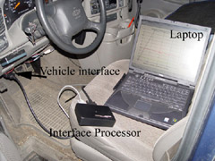
Figure 11
Examples of data that can be recovered are shown
in Figures 12 through 15. Figure 12 is a graph of the
data from a non-deployment event (a deceleration
of the vehicle that is not sufficient to deploy the air
bag.) The sensing diagnostic computer stores
vehicle data from up to 5 seconds before an
electronic logic decision is made to deploy.
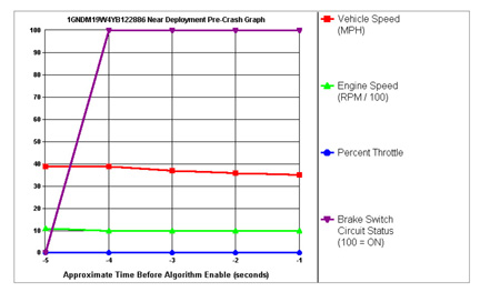
Figure 12
Figure 12 shows the brakes being applied and the
vehicle decelerating from about 39 MPH to 36
MPH from 5 to 1 seconds before algorithm enable
(the computer program decision to deploy.) Engine
RPM and throttle position are also graphed. Figure
13 shows additional information retrieved. The air
bag warning light was not lit, indicating no faults
found in the diagnostic circuitry. The driver’s seat
belt was buckled. The passenger air bag suppression
switch circuit was not suppressed, and 6815 ignition
cycles had occurred at the time the data was
recorded. This data suggests that the system
operated properly by not deploying the air bag.
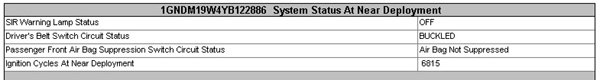
Figure 13
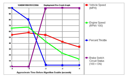
Figure 14
Figure 14 shows a similar data graph from an
accident where the air bag was deployed. After
nearly full throttle operation, the brakes are
activated and the throttle closed to the idle position.
Vehicle speed is characteristic of severe braking.
The impact speed is near 30 mph. Since the airbag
was deployed, the velocity change data is recorded,
as shown in Figure 15.
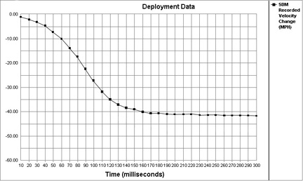
Figure 15
The velocity or speed change is the speed at a
particular time minus the initial speed. If a vehicle
strikes a barrier at 30 MPH and stops after the
impact, the velocity change is 30 MPH. If a vehicle
strikes a barrier at 30 MPH and bounces back at 3
MPH, the change in velocity is 33 MPH. In Figure
15, the total velocity change during the accident
was about 43 MPH, a severe accident where the air
bag should deploy. Since the striking velocity was
at about 30 MPH and the change in velocity was
about 43 MPH, this indicates that the subject
vehicle was pushed backward at about 13 MPH
after the accident with the other, larger vehicle.
CONCLUSION
When claims issues revolve around reconstructing
automobile accidents, an inspection and testing of
the vehicle can yield valuable information that can
act as a basis for acceptance or denial of a claim.
The measured speeds and speed changes stored in
the on-board computer (black box) will trump most
calculated estimates. A claimant may state that his
vehicle was traveling at 30 MPH prior to impact
when on-board data shows clearly that the vehicle
was traveling at 62 MPH. Injuries sustained by a
claimant may be explained by the buckled and
unbuckled status data stored in the computer.
Claims of alleged defects in the air bag system can
be investigated. As always, permission to download
the on-board computer data may be required before
proceeding with an investigation.