VEHICLE ACCIDENTS CAUSED
BY DEFECTS
Throttle Control System
By
Charles C. Roberts, Jr., Ph.D., P.E.
Vehicle
accidents can occur as a result of defects and are often at the root of an
insurance claim. It is not unusual for an insured to blame an automobile
accident on a defect related to a vehicle (my brakes failed, the accelerator
stuck, a tire detached, etc.) The claims analyst typically investigates the
existence of a defect in order to determine liability or the propensity of
subrogation. The extent of the many possible defects that may exist in an
automotive vehicle are numerous and beyond the scope of one article. This is a first in a series of articles
dealing with vehicle defects that can cause an accident. The subject matter of this article covers
case studies of actual accidents involving a defect in the throttle control system.
Figure
1 shows three typical throttle control systems in automotive vehicles. The
mechanical system is a classic, having been developed since the early days of
the automobile. Rod linkages are connected to the throttle plate to actuate the
throttle with a return spring whose purpose is to close the throttle plate once
the driver’s foot is removed. The cable throttle control system is a more
recent design where a cable controls the throttle via a pulley. A torsional spring returns the throttle plate to a closed
position once the driver’s foot is removed. The third system is a “fly by wire”
or electronic control system where an accelerator position sensor sends a
signal to an electronic control module (ECM), that sends a signal to a throttle
position motor, which in turn sets the throttle position.
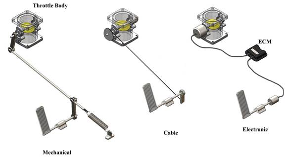
Figure 1
The following case studies
illustrate problems with throttle control systems that have caused an accident.
A common throttle system malfunction is the engagement of the accelerator pedal
in the vehicle floor mat as shown in Figure 2 (upper photo). The driver of this
vehicle pressed the accelerator pedal to the floor, and when the pedal was released,
the vehicle continued to accelerate at high speed, eventually causing an
accident. There are several reasons for the engagement of an accelerator pedal
under a carpet. The carpet could be out of position, improperly installed, the
wrong size or improperly designed. Downloading the sensing diagnostic module
(black box) can show evidence of the malfunction. In one instance, a dealer had substituted
another floor mat for the factory installed floor mat, causing the malfunction.
In another case, the insured supplied the floor mat. Clearly subrogation
potential is dependant on the claims analyst’s investigation tying down the
facts regarding the floor mat placement.
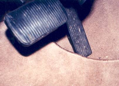
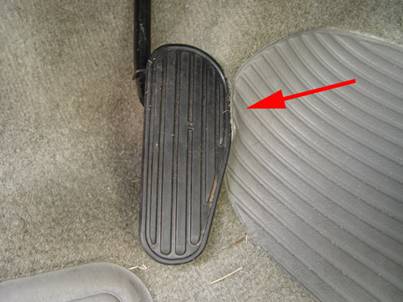
Figure 2
Figure 2 (lower photo) shows an
accelerator pedal engaged in the polymer wear pad at a sewing seam. When the
accelerator pedal was pressed it readily engaged in the wear pad which resulted
in uncontrolled acceleration and an accident. This is a design related defect.
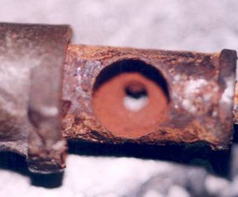
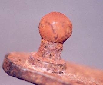
Figure 3
Another cause of throttle malfunction
is corrosion of throttle linkages. Figure 3 shows a small ball joint that is
part of a throttle assembly near the throttle plate. The ball joint eventually
became difficult to articulate due to corrosion, causing the throttle to remain
open after the accelerator pedal was released, which resulted in an accident.
In this particular case, corrosion resistive plating of the metal parts was
insufficient and was found to be a manufacturing defect.
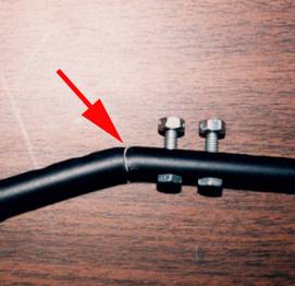
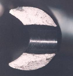
Figure 4
Figure
4 is a view of a hand throttle linkage that was part of a manual throttle system
used by disabled drivers. The linkage connected the accelerator pedal to a hand
lever that would operate the throttle. While driving the vehicle, the throttle
link failed, causing an accident. In the left photo of Figure 4 the arrow
points to a fracture that occurred at a bend in the linkage. The right photo
shows the fracture surface of the aluminum rod, with evidence of metal fatigue.
Apparently, the installer of the system had bent the aluminum rod in order to
facilitate installation, causing a crack that initiated a progressive failure scenario.
The bend occurred at a hole provided for bolts used to attach the rod to the
throttle system. Metallurgical
examination determined that metal fatigue had reduced the rod cross section to
the point of failure. This is an installation related defect with subrogation
potential.
Electronic throttle control
systems are being designed into more recent vehicles and may become a more
prevalent throttle control system. Failure of electronic components may require
analysis of an event data recorder on the vehicle, which will often require a
manufacturer to download the data since the software is usually proprietary.
However, the mechanical parts of the electronic throttle control system can
exhibit failure modes similar to those shown in the case studies.
Figure 5 is a screen grab from
a crash data recorder download where a malfunction of the accelerator was
suspected. From 5 seconds to 1 second before impact, the throttle position was
constant at approximately 72% (solid blue line). The brakes had been applied (lavender line)
and the vehicle was slowing from approximately 62 MPH, at 5 seconds before
impact, to 50 MPH at 1 second before impact. The engine was not at idle and
varied in RPM from 3200 to 3600 RPM. With the driver’s foot on the brake, the
percent throttle opening should decrease to near zero as indicated by the
dashed blue line. The data indicates that the throttle stuck in a position of
approximately 72%, which resulted in uncontrolled acceleration and an accident.
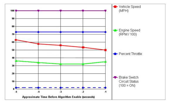
Figure 5
In
cases where throttle control failure is claimed or suspected, it would be
prudent for the claims analyst to inspect the vehicle to determine if evidence
suggests a malfunction that could result in recovery from a party to a legal
action. The evidence should be preserved for future inspection by various
experts, including those of the manufacturer.