Failure Analysis of a Valve
By
Charles C. Roberts, Jr., Ph.D., P.E.
Valves
are fluid flow control devices used in a variety of industries. There are many
different types of valves, with two major categories
being multi turn valves (typical home water faucet as an example) and quarter
turn valves (typical gas shut off on a home furnace as an example). This
article deals with a butterfly valve, a quarter turn type valve, depicted in
Figure 1. A butterfly valve incorporates a circular disk that when rotated perpendicular
to the long axis of the pipe blocks the flow of fluid (Figure 1A). The valve handle indicates this condition
when it is placed perpendicular to the long axis of the pipe. When the disk is parallel to the long axis of
the pipe (Figure 1B), it offers little resistance to fluid flow. The handle is
parallel to the water pipe indicating wide open and maximum flow. The butterfly
valve can act as a control valve with the handle in intermediate positions.
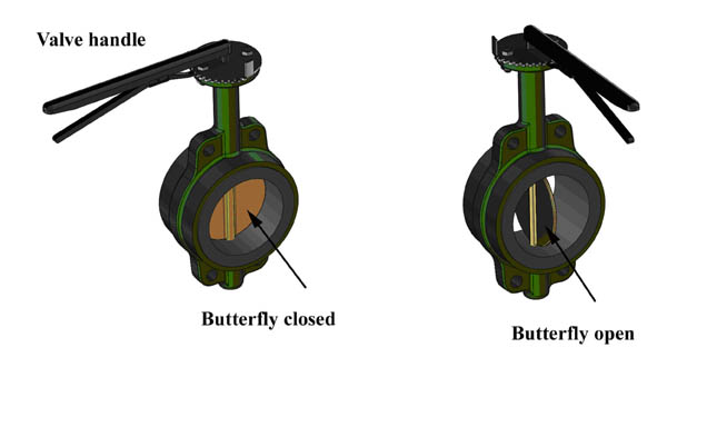
Figure 1
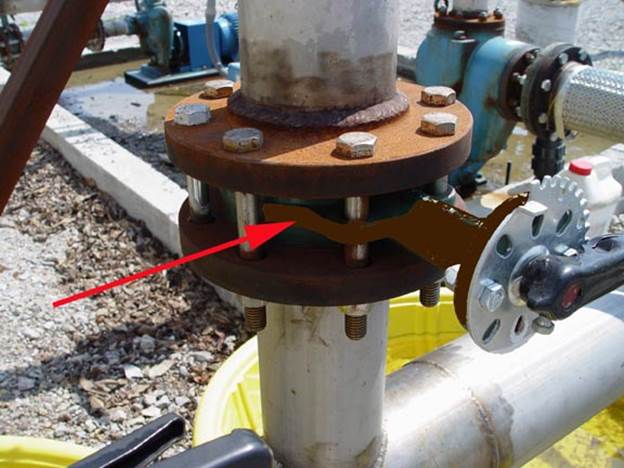
Figure 2
Figure
2 is a view of a butterfly valve in an industrial chemical facility. The red
arrow points to the butterfly valve body sandwiched between two flanges. The
valve handle is at the right and in the apparent closed position. A large loss
occurred when incompatible herbicide chemical liquids were inadvertently mixed,
causing a large crop loss when the mixture was applied to farm fields. Analysis
of the system lead to the newly installed butterfly valve shown in Figure 2 that
appeared to be the cause of the accidental mixing of chemicals.
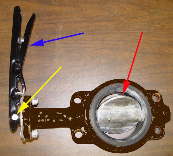
Figure 3
Figure
3 shows the butterfly valve removed from the system with the valve operating
handle in the closed position perpendicular to the direction of the flow (blue
arrow). In this position, the butterfly should be fully closed, but in fact, it
is partially open as shown in Figure 3 (red arrow). There was no evidence to
suggest that the butterfly was forced into this position by some other
influence such as shipping or installation. The bolt used to secure the valve stem to the
handle (yellow arrow) was found to be improperly located on the valve stem
shaft. This resulted in the butterfly valve being partially open when the valve
handle was in the closed position, as shown in Figure 3. This allowed the inadvertent mixing of
incompatible chemicals, which caused the crop loss. The improper assembly of
this valve handle suggests a manufacturing defect and potential subrogation.
Published in Claims 2014