ANALYSIS OF A WATER PIPE
COMPRESSION FITTING FAILURE
By
Charles C. Roberts, Jr., Ph.D., P.E.
Figure 1 is a view of a typical plumbing compression
fitting used to splice plumbing pipes. In some installations with long pipes
and limited access, replacement of a section of pipe is often accomplished with
two compression couplings at each end of the replacement pipe.
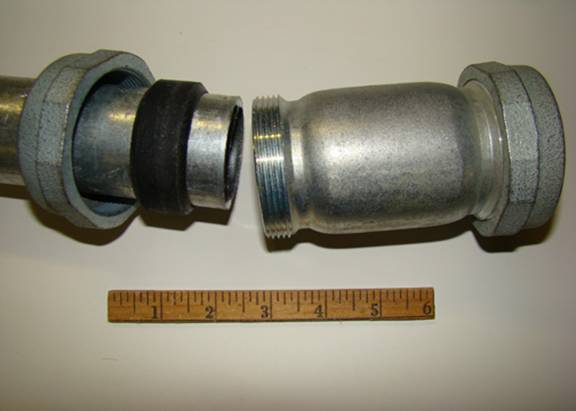
Figure 1
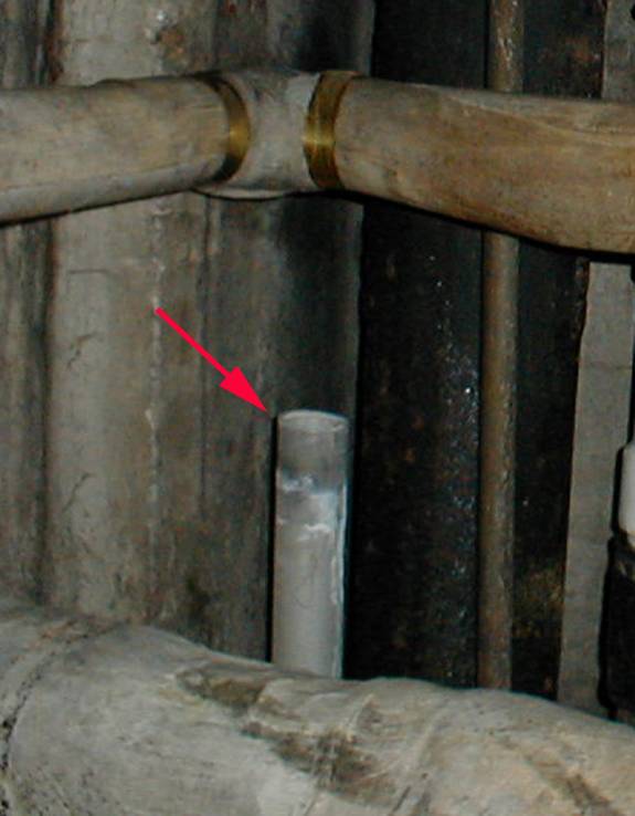
Figure 2
Care in the installation of compression couplings
should be exercised as illustrated in the following case study. Plumbers
repaired a pipe that was leaking, as a result of corrosion, on the third floor
in an old, historic building. A section of the pipe was removed and replaced
along with two compression couplings, one at each end. The plumbers finished
the work and left. Approximately 3 days later, one of the compression fittings parted,
causing a significant water loss. Figure 2 (arrow) shows the pipe that had
parted from the compression fitting.
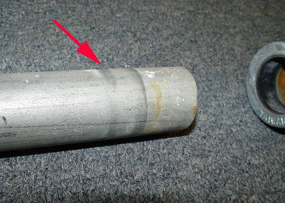
Figure 3
Figure 3 shows the parted pipe and the outline of the
compressed rubber seal of the compression fitting. The compression fitting
worked its way off the end of the pipe, allowing water to pour down several
floors of the building.
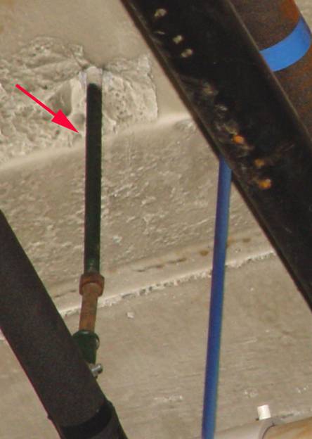
Figure 4
Further inspection of the vertical pipe in the
basement yields a clue to the failure of the coupling (Figure 4). The vertical pipe that pulled loose of the
coupling (arrow, Figure 4) terminated at a T fitting with a larger pipe. The
hangers of the larger pipe had deteriorated, rendering the large pipe virtually
unsupported other than the support of the vertical pipe that failed. The
friction of the vertical pipe through the concrete floors and the deteriorated
pipe hangers were the only restraint holding the large horizontal pipe in
place.
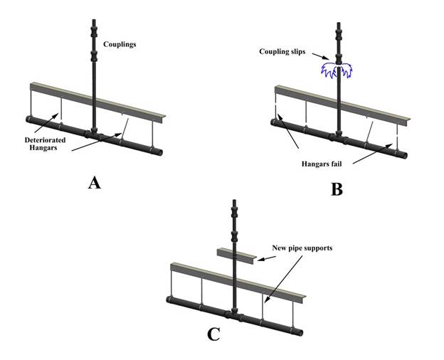
Figure 5
Figure 5 illustrates the failure scenario. Figure 5A
shows the system with the coupling in place, shortly after the plumbers had
left the job site. Figure 5B shows that the vertical load carrying capacity of
the pipe has been significantly reduced with the usage of the compression
fitting. Because of the limited axial force capacity of the vertical pipe when
using compression fittings, the deteriorated hangars failed, shifting the load
to the vertical pipe and couplings. The couplings could not support the load,
slipped and parted. It should be noted that compression fittings require
restraints against axial movement brought on by weight and vibration related
forces. Unlike threaded fittings,
compression fittings can seal properly but still slip out of position as a
result of forces on a pipe. In this case, the plumbers failed to properly
restrain the repaired pipe when using compression fittings. Figure 5C shows
that a restraint for the vertical pipe and hangar repair should have been
performed before job completion. A quick inspection of the pipe in the basement
would have revealed the necessity to repair the pipe hangers and restrain the
repaired pipe. No defects were noted in the compression fittings that could
have caused the failure. Analysis of the evidence suggests that the underlying
cause of the failure was improper repair of a water pipe.