The Physical Designer’s Nightmare:
Chaffing of Electrical Wire Insulation
By
Charles C. Roberts, Jr., Ph. D., P.E.
The
design of electronic equipment takes place through the efforts of circuit
designers who develop the parameters for an electronic system, and physical
designers who deal with the layout of the electronic equipment. The physical
design of wiring systems is an important aspect of their development. Choice of
wire type, wire layout, wire supporting means, and wire restraints are typical
design parameters used in the physical design of electrical equipment. An
important part of this design process is the phenomenon of electrical wire
insulation failure, as a result of chaffing.
Chaffing is the wearing of electrical wire insulation by a variety of
means, as shown in Figure 1.
Figure
1A shows classical vibratory wear of wire. Here, the designer has allowed the
wire to rest on a surface that vibrates, causing insulation breakdown and
eventually an electrical fault; assuming that the surface is at a different
electrical potential, which is likely the case. In Figure 1B, a wire is routed
over an abrading surface and is chaffed from thermal expansion and contraction
as a result of environmental thermal effects as well as resistive heating when
the electrical system is active. Figure 1C shows a mechanical device whose
surface moves relative to the wire insulation, causing chaffing. Figure 1D
shows pinching of the wire, causing insulation breakdown often accelerated by
high temperatures and tensile loads in the wire.
In order to illustrate
typical chaffing problems, the following is a sampling of wiring malfunctions
brought on by chaffing.
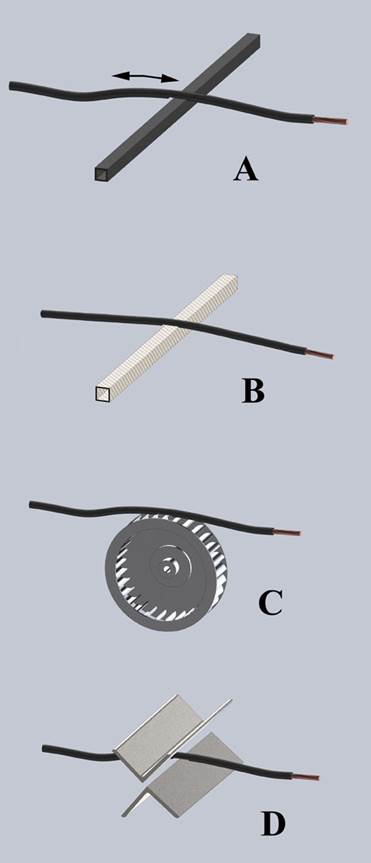
Figure 1
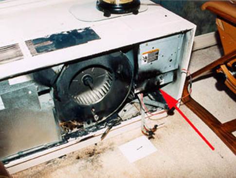
Figure 2
Figure 2 shows a fan system
with a fire origin (arrow) at control wiring lying against a sheet metal
support bracket. Wire chaffing has occurred, developing an electrical fault and
causing the fire. In many instances, the fuse or breaker would interrupt the
circuit, stopping any further damage to the device. In other instances, the
electrical fault may have sufficient resistance to limit current and not blow a
fuse or trip a breaker. It should be noted that energy dissipation density at
the fault area causes the fire, not only the amount of electrical current. A relatively small current driving a fault
through a very small area can cause high temperatures and ignite combustible
material, resulting in a fire and significant damage.
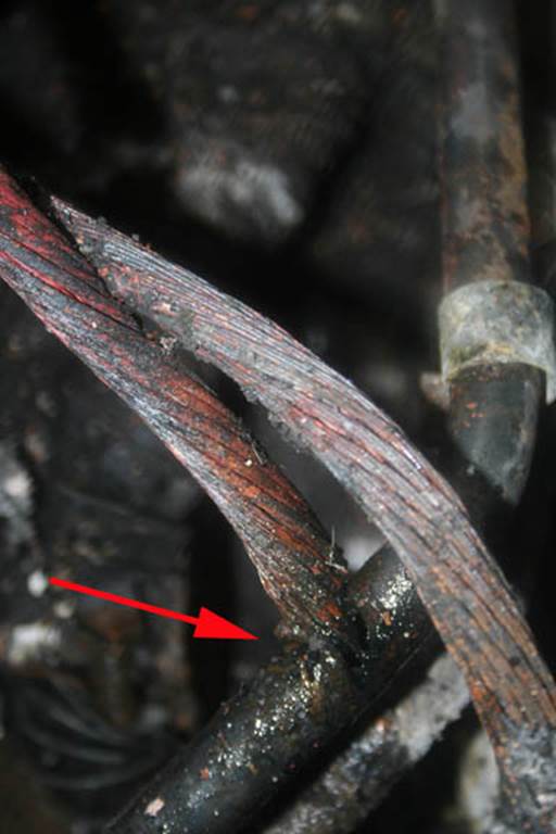
Figure 3
Figure 3 depicts an unfused
battery wire that was chaffing against an hydraulic
line in a large vehicle. The wire chaffed, faulted against the hydraulic tube and
formed a penetration through the tubing wall, in a manner similar to electric
discharge machining (EDM). The resulting hydraulic fluid pressure release
caused a spray of hydraulic fluid, which was ignited, destroying the
vehicle.
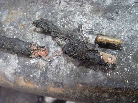
Figure 4
Figure 4 shows the remains of
an engine block heater cord located at the front bumper of a pickup truck. It
is not unusual for vehicle owners to back out of the garage without unplugging
the cord. Chaffing occurs quite readily, which caused an electrical fault, a
fire and total destruction of the vehicle and garage.
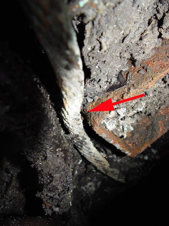
Figure 5
Figure 5 is a view of a battery
wire that faulted against an engine mount near the exhaust pipe on a large
truck. Vibration and softening of the electrical insulation from exhaust pipe
heating resulted in an electrical fault, which ignited combustible material and
destroyed the vehicle.
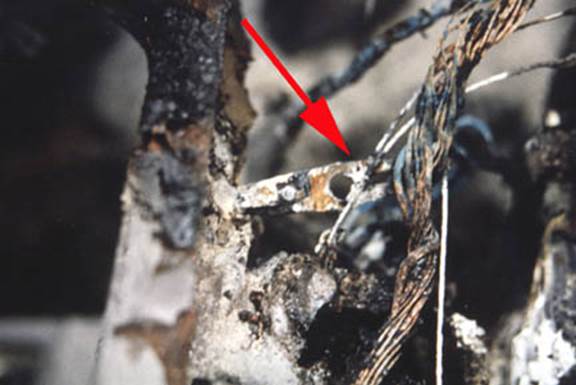
Figure 6
Figure 6 is an example of
mechanical interference with wiring. A bell crank for a heater vent in an
automobile was moving back and forth under normal usage, chaffing the wiring
harness that eventually faulted, causing a fire and destruction of the
vehicle.
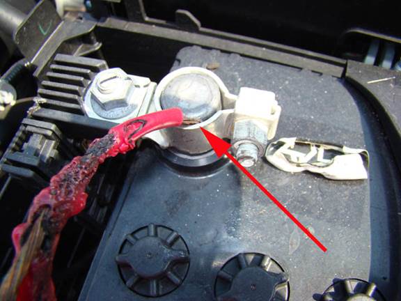
Figure 7
When analyzing the remains of
equipment, an item that tends to attract one’s interest is the existence of
non-factory related modifications.
Figure 7 depicts a non-factory related connection to a battery post.
Following this add on wire, which lead to the point of origin of the fire,
verified an unsecured condition that was subject to vibration and consequent chaffing.
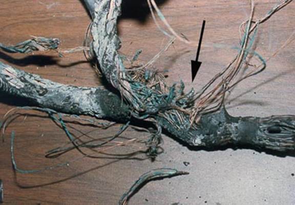
Figure 8
Wiring bundles or harnesses
have their own set of problems. In Figure 8, a power wire in the wiring harness
faulted, causing severe damage to a piece of equipment. Thermal expansion and
contraction from electric current in the power wire inside the harness caused
chaffing and an electrical fault.
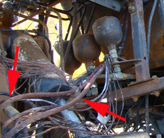
Figure 9
In Figure 9, power wires
(arrows) are draped over various parts of a vehicle, a poor physical wiring
design. One of the wires chaffed, faulted, and the vehicle was destroyed by
fire. A more organized physical design of wiring, along with appropriate stand
off clamps, would have prevented this failure.
These case studies serve to
illustrate many physical wiring design deficiencies that caused severe damage
to equipment. Some design related tenants come to mind:
1. In the absence of a vibratory environment, cyclic
movement from thermal expansion and contraction can still occur, causing
chaffing. Leave an appropriate amount of wire slack to avoid wire tension
during thermal contraction (Figure 1B).
2. Interference of electrical wiring with mechanical
apparatus is a cause of chaffing requiring proper routing and restraint (Figure
1C).
3. In vibratory environments, usage of cable clamps and
other restraining devices should be considered as part of the design. Avoid
laying cables randomly over a machine (Figure 9) and relying on the quality of
the insulation to prevent a malfunction.
4. Attention should be paid to wire bundles that contain a
mixture of low current and high current wiring. Thermal cycling can cause
relative movement between wires in a bundle or harness. Also, different types
of wire insulation can aggravate chaffing from relative movements. Finally,
routing wiring horizontally, rather than vertically, may limit damage to
equipment as a result of a fault.
Vertical wiring harnesses burn more readily than horizontal wiring
harnesses since convective forces drive combustion gases vertically, easily
increasing the chance of fire development.
5. Avoid routing wires in high personnel traffic areas
such as under carpets. Avoid having wiring harnesses routed in an area where it
is convenient to be used as a hand hold device during maintenance or other
activity.
6. When using stand off clamps or other means of restraint, care should be taken not to pinch individual
wires in a bundle, when securing the clamp.
7. Particulates, such as metallic debris, should not be
in the vicinity of wiring harnesses since the debris can accelerate chaffing as
a result of thermal expansion and vibratory means.
Many
references are available on physical design of wiring, examples of which are:
1.
Aircraft
Electrical Wiring Interconnect System Best Practices, Federal Aviation
Administration, Revision 2.
2.
Society of
Automotive Engineers Standards on Wiring.
3.
National Electric
Code.
Published in Machine Design 2014