HEAT RELATED DAMAGE PATTERN ANALYSIS
FOR
FIRE ORIGIN ANALYSIS
By
Charles C. Roberts, Jr., Ph.D., P.E.
Heat related damage
patterns at a fire scene yield clues as to where a fire originated. This
article is a third in a series that discusses burn patterns and interpretations
when attempting to determine the origin of a fire. The first article (Reference
1) dealt with burn and damage patterns on buildings and interpretations of the
damage. The second article (Reference 2) dealt with selected case studies
regarding analysis of burn patterns. This third article presents additional
case studies not mentioned in the previous two articles.
Photographs
facilitate the discussion of burn patterns and are unique to a particular loss.
Consequently, this article contains several photos of burn patterns from actual
losses in a picture book format to act as a reference when analyzing a
particular fire related claim.
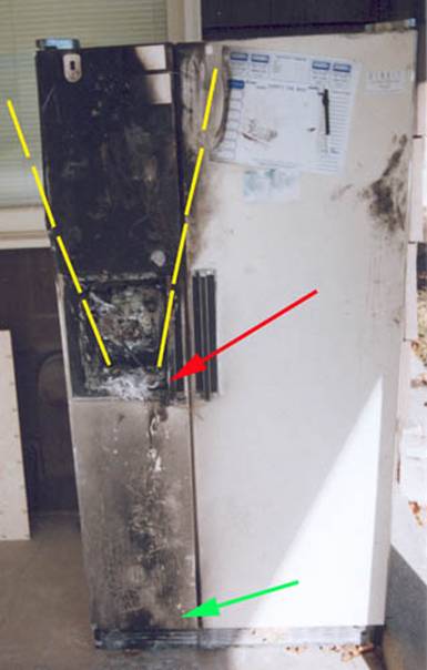
Figure 1
A review of fire
analysis methodology suggests that the classic V thermal damage pattern is used
by analysts to determine the origin of the fire, the base of the V being the
likely origin of the fire. The damage
that forms the shape of the V can be a result of soot deposition, direct flame
impingement, combustion of a fuel or melting. Fire development by convective
means often results in flames or hot gases rising and diffusing upward, forming
a V. The example in Figure 1 illustrates the base of the V (yellow dashed line)
which is at the ice dispensing unit (red arrow). There is some minor damage
below the V as a result of “drop down” debris (green arrow) often discounted as
an indicator of the fire origin. The red arrow points to the probable origin of
the fire. The inherent assumption is that fire generated natural convection
(gas movement as a result of gas density differences) has resulted in a V shaped
damage pattern. Forced convection such as wind or mechanical influences can
distort the pattern such that it does not resemble a V, adding difficulty in
determining the fire origin.
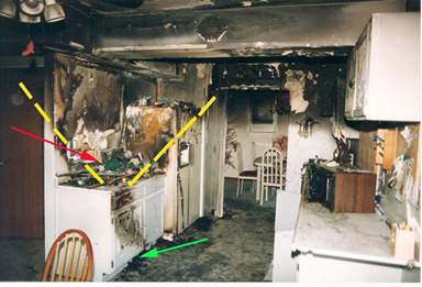
Figure 2
Figure 2 serves to
illustrate a wider burn pattern with similar characteristics (yellow dashed
line). This V pattern suggests a fire origin at the red arrow in the vicinity
of a stove top. There is some drop down burning debris (green arrow) as in many
instances, but the significant base of the V is on top of the stove. The typical smoke cloud pattern is shown on
the walls, illustrating the interface between burning gases and the clear air
below. These burned areas are not at the fire origin since they are high and
not low, in the vicinity of the V.
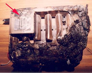
Figure 3
Figure 3 is a top
view of a battery charger that was near the origin of a fire. The polymer housing at the right lower corner
of the charger is the most severely damaged area. No batteries were being
charged at the time of the fire but the unit was plugged into a wall
receptacle. The electronics driving the battery charger are at the upper left
corner and undamaged (red arrow). The direction of heat transfer appears to be
from the lower right to the upper left. There is no evidence of decreasing
thermal damage from the upper left to the lower right on the charger, alluding
to the conclusion that the fire origin is likely not at the charger but to the
lower right, outside the polymer enclosure.
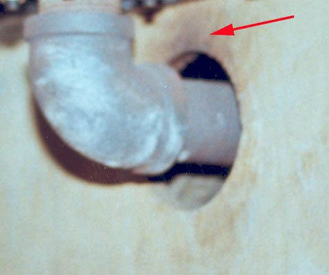
Figure 4
Some thermal patterns
develop before a combustible material is ignited, as shown in the pyrophoric
decomposition of wood: the chemical decomposition of wood brought on by
constant or periodic heat application (Figure 4). The exhaust pipe in an auxiliary heater has
caused excessive heating of the wood enclosure and a brown shade to the wood
surface has developed (red arrow). This heating, if unchecked, will eventually
result in ignition of the wood and a fire. Examining this exemplar installation
(Figure 4) was certainly helpful, since it explained why the fire started next
to the heater in another identical installation.
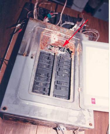
Figure 5
A unique thermal
damage pattern is that of metal erosion by electrical arc as shown in Figure 5.
A fault current had developed near the top of the electrical panel (red arrow)
causing ionization of the metal. This was the most severely damaged area on the
panel with some charring of the mounting board, suggesting the top of the panel
to be the fire origin. As with many other forms of electrical malfunction, the
mere existence of arc erosion is not necessarily the origin of the fire. Arc erosion damage should be evaluated along
with other burn patterns in the area. In this case, the surrounding burn
patterns are less severe than that on the panel, leading one to theorize that
the panel is the likely origin of the fire.
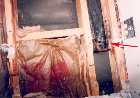
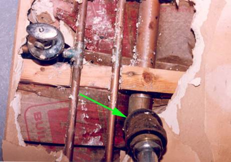
Figure 6
Some thermal patterns
at the fire origin can exist inside a wall, which may not be initially
visible. Figure 6 (upper photo) shows a
vertical burn pattern on paper backed fiberglass insulation up through a wall
(red arrow). The lower photo shows a pipe joint that had been soldered prior to
the fire (green arrow) and a low burn area on the paper backed thermal
insulation. Shortly after the plumber left the home, a fire developed. The
origin of the fire appears to be at the pipe joint since there is no other low
burn damage in the area. The fire easily spread up the wall into the attic
above, burning the paper backing of the insulation. The lack of a fire break in this vertical
cavity aggravated the situation by allowing rapid spread of this fire.
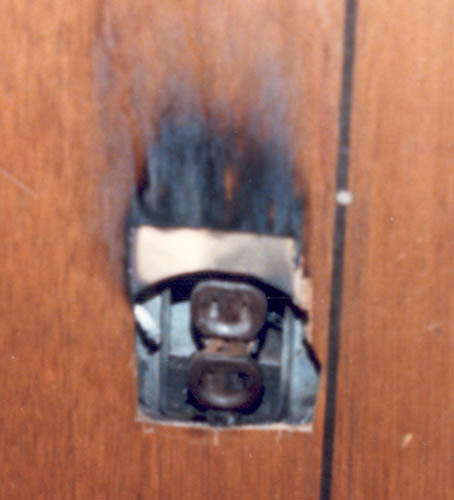
Figure 7
The thermal pattern
in Figure 7 is a result of smoke transport through or up a wall and exiting at
gaps around an electrical receptacle. There is no damage to the electrical
wiring or receptacle. Particulate
deposition along a smoke path may be mistaken as a fire origin. The absence of
damage to the receptacle should invoke caution in opining that this area is a
fire origin.
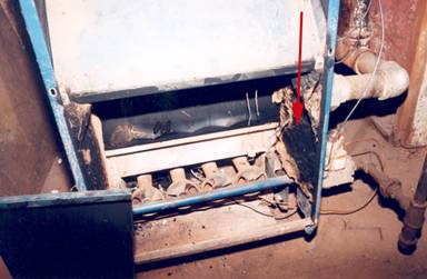
Figure 8
Thermal damage from a
furnace malfunction is of interest to the analyst. In Figure 8, the soot
deposition at the side and above the furnace (red arrow) is symptomatic of
flame roll out, a phenomenon usually caused by insufficient flue vent area. An
inspection of the chimney revealed deteriorated masonry blocking the flue vent,
causing furnace flames to roll out the front of the furnace and ignite paper
garbage in a plastic container. Modern furnaces have “spill” switches that shut
down the furnace if flame roll out occurs, but many older furnaces do not. Defeating
the function of “spill” switches on modern furnaces has been known to occur and
can result in flame roll out patterns like that shown in Figure 8.
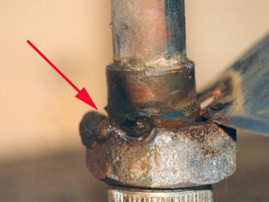
Figure 9
Figure 9 is an insulated
plumbing fitting (dielectric union) attached to a water heater. It is insulated
to reduce the onset of galvanic corrosion between the two dissimilar metals,
copper and iron. After a lightning strike on the home, this damage was found
along with other evidence of high voltage electrical current. The resistance of
the dielectric union, in concert with high current, caused excessive heating of
the outer nut and severe arc damage.
This is not a result of soldering, which supplies insufficient heat to
cause such damage to iron, but was most likely a result of high current flow,
characteristic of a lightning strike.
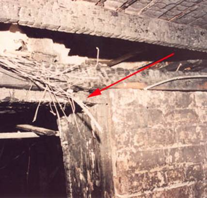
Figure 10
Figure 10 depicts a
door frame in a basement area with a fire origin at the upper part of the
frame. Char depth is most severe in this area (red arrow). Electrical wiring
above, at the door frame, shows evidence of arcing, probably as a result of
continuously chaffing against the door, causing insulation breakdown,
electrical malfunction and a fire. Char damage to wood members tends to
decrease as one moves away in any direction from the
location of the red arrow, a good fire origin indicator.
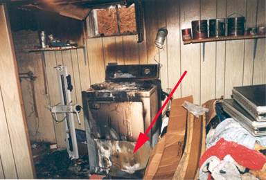
Figure 11
Figure 11 shows a
burn pattern on a clothes dryer with an approximate
origin at the red arrow. The low burn and badly oxidized sheet metal on the
dryer suggest that a malfunction inside the dryer caused a fire. There is
relatively little damage around the dryer which supports the opinion that the
dryer caused the fire.
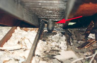
Figure 12
A fire origin was
found at a plumbing stack in a home after a lightning strike (Figure 12). There
was evidence of burning in the form of char on roof sheathing around the
plumbing vent only, with the absence of any other burn patterns throughout the
home. There were no man-made electrical or mechanical ignition sources in this
area. Char depth is most severe right next to the plumbing vent and decreases
away from the vent.
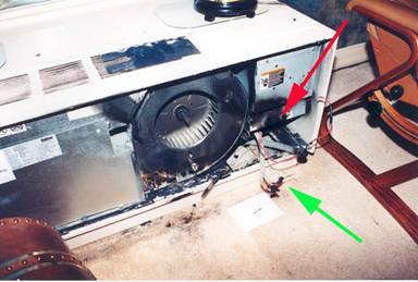
Figure 13
Figure 13 depicts a
relatively small burn pattern inside of a heating unit. The fire origin (red
arrow) was located at severely damaged electrical wire (green arrow) that was
routed around a sharp metal corner where a wire had chaffed and shorted. The
blower had sucked burning debris and smoke into its intake and spread it around
the apartment, causing significant smoke related damage. It should be noted that the forced air flow has
affected the natural convective V pattern which was distorted to the left as a
result of the blower.
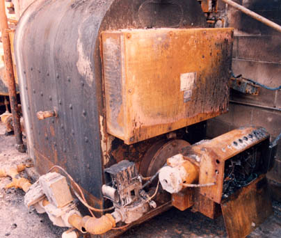
Figure 14
Thermal patterns on
overheated boilers tend to be uniform since the whole unit tends to be overheated.
In Figure 14, we see a boiler that overheated, causing a fire and severe damage
to a building. A low water cut off control was found to have malfunctioned,
causing the over heating. The dark grey, high temperature oxide is noted on the
outer shell of the boiler, which is consistent with overheating.
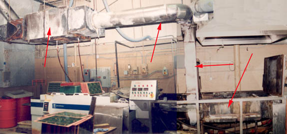
Figure 15
Figure 15 is a photo
of a badly damaged electronic processing machine which shows uniform burn
patterns throughout the machine and duct work (red arrows). This is indicative
of ignition of combustible vapors in the machine and exhaust duck work. Burn
patterns of this nature are often not definitive as to the origin of the fire,
other than that a combustible vapor was ignited inside the machine.
Heat related damage
pattern analysis is classically used by investigators to opine as to where a
fire started. Among many other tools, V
pattern analysis, evaluation of char depth gradients, evaluation of melted
material and observation of smoke deposition have been illustrated in the 15
case studies presented in this article. These 15 case studies serve as specific
examples of heat related damage analysis but do not exhaust the myriad of
conditions that exist in the field. Each
fire case is unique, but the burn pattern analysis methods are similar, as
illustrated above.
1.
"Burn
Pattern Recognition for Fire Origin Analysis," Insurance Adjuster Magazine
(later Claims Magazine), July 1987. (http://croberts.com/Burn-Pattern-1987.htm)
2.
“Thermal
Pattern Analysis: Investigating Fire’s Fingerprints,” Claims Magazine, June
2000. (http://croberts.com/burn.htm)